Services
Structural BIM Services
Precise structural modeling for steel, concrete, and timber systems with fabrication-ready details and complete coordination.
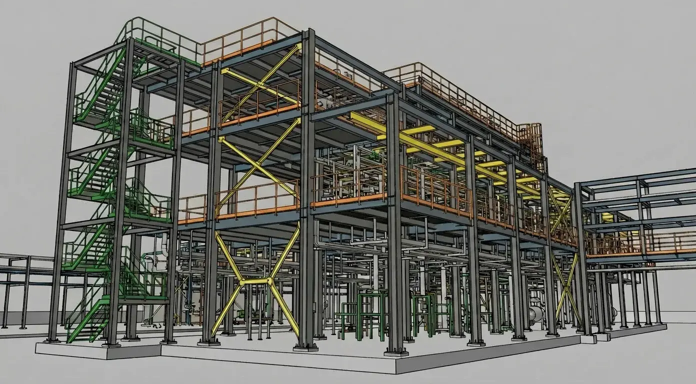
Models the Fabricator Can Read
A structural model is eventually read by people who will cut steel and bend bar from it. We model members, connections and reinforcement to the Level of Development the package actually requires, carrying the member marks, type naming and parameter data your schedules and downstream detailers depend on.
We work inside your template and your BIM Execution Plan as a task team. The engineer of record keeps design authority, sizing and sealing; we produce the geometry, the data and the documentation that sits behind that design.
What We Offer
Structural Scope
From the design model through to the detail a fabricator or a rebar shop can work from.
Structural modelling
Framing, foundations and slabs modelled from the engineer's design in your template, with grids, levels and member marks that match the issued documents.
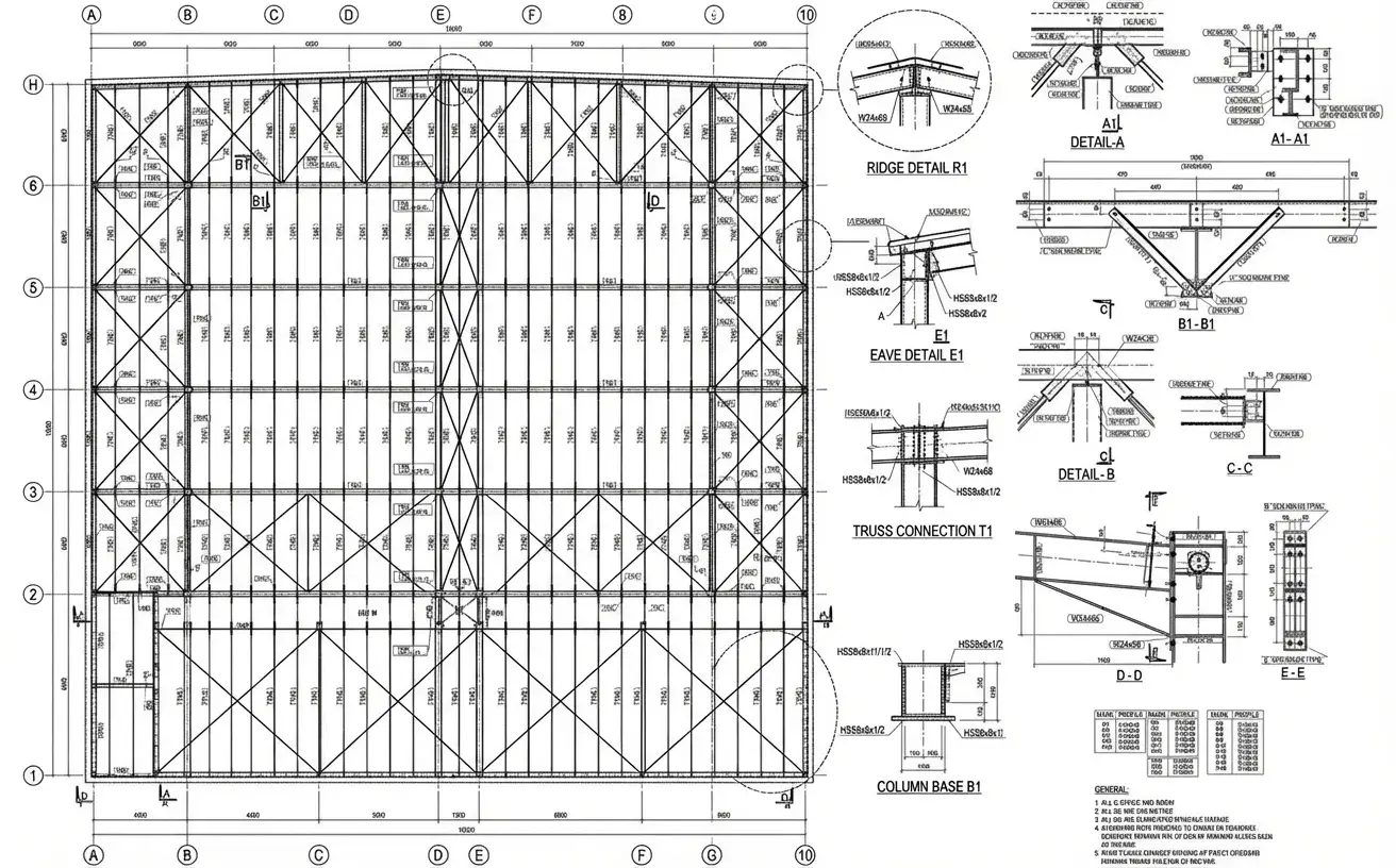
Steel detailing support
Connection modelling and detailing support that fits the fabricator's workflow, produced from a coordinated model and checked back against the connection design.
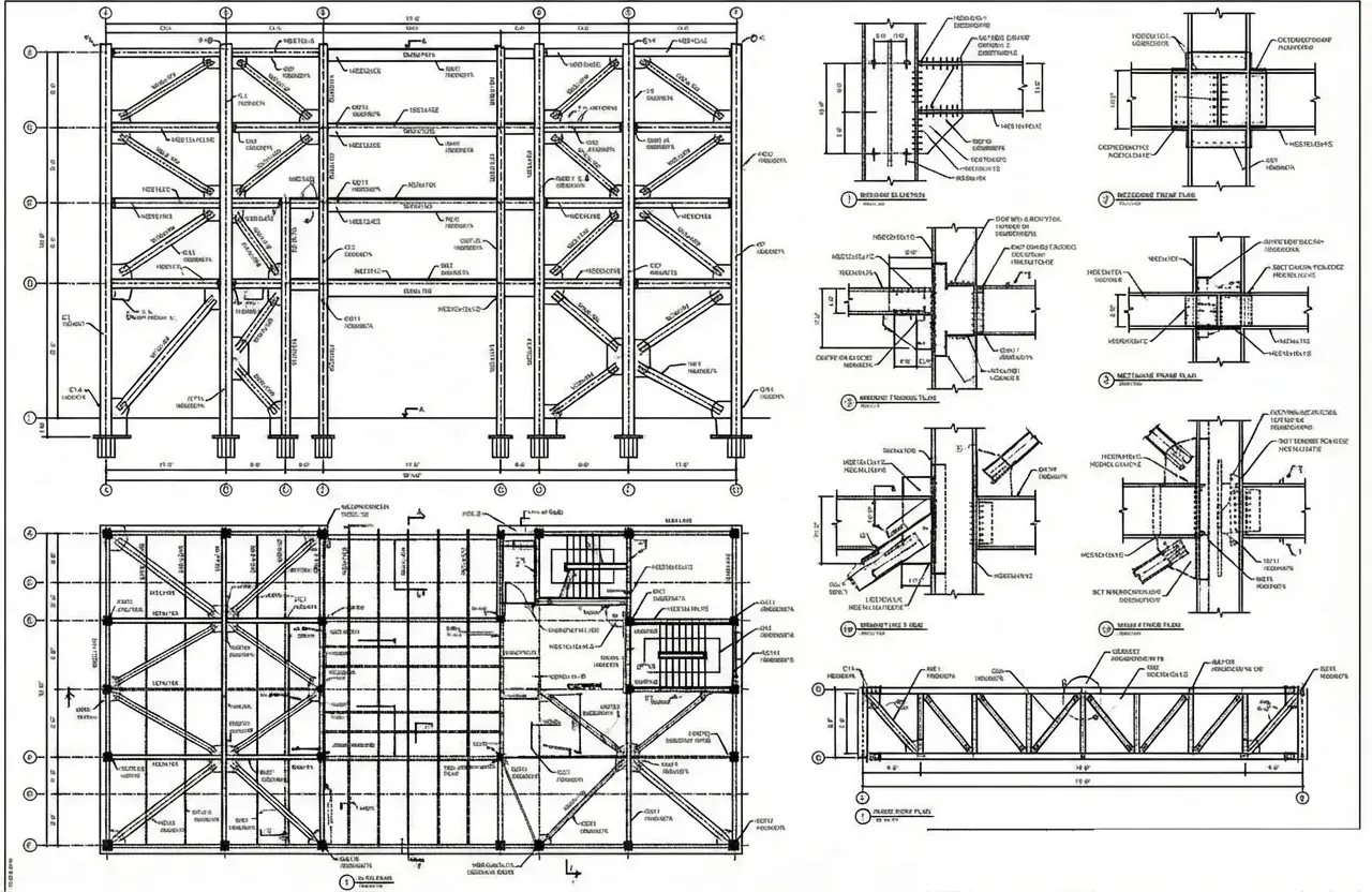
Reinforcement modelling
Rebar modelled as placed rather than as drawn, so bar schedules, laps and congestion at the difficult joints are visible before the cage is tied.
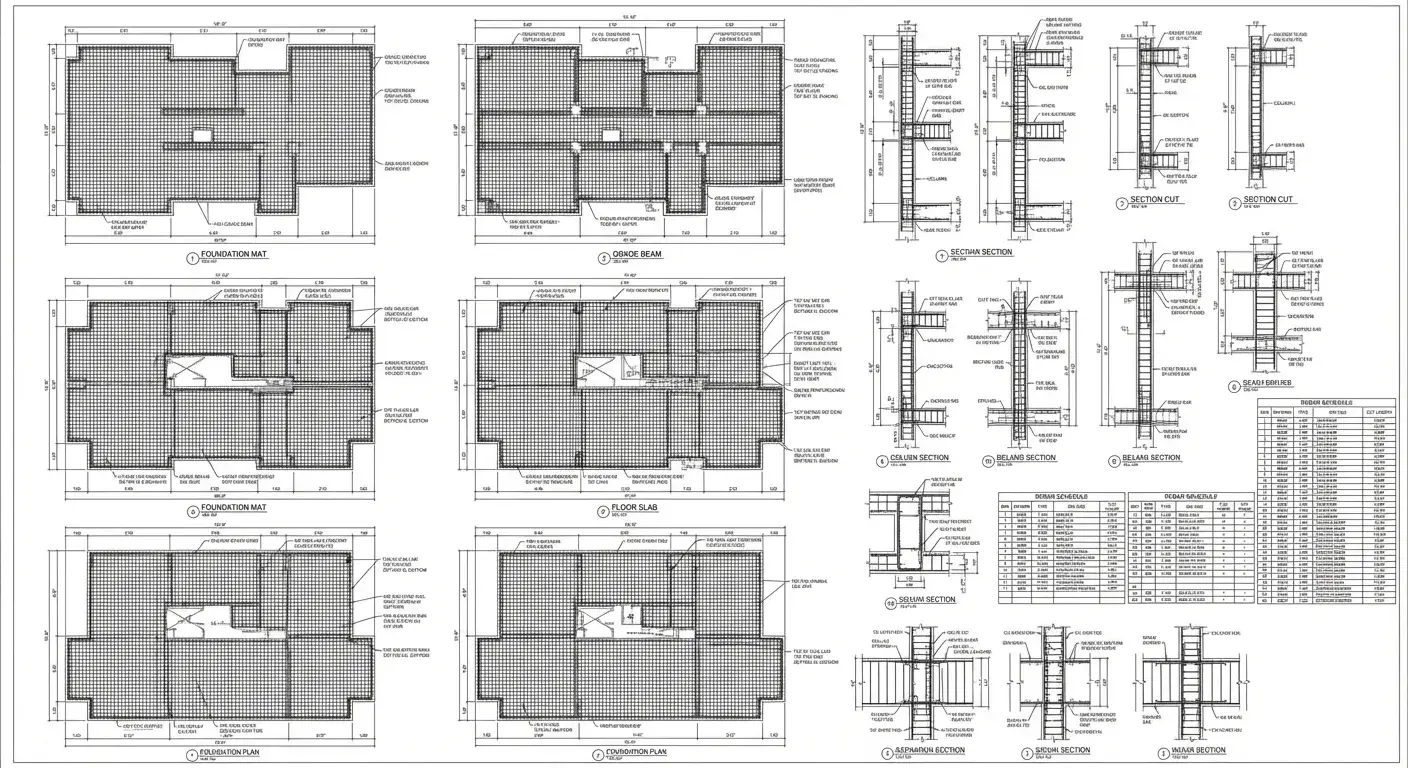
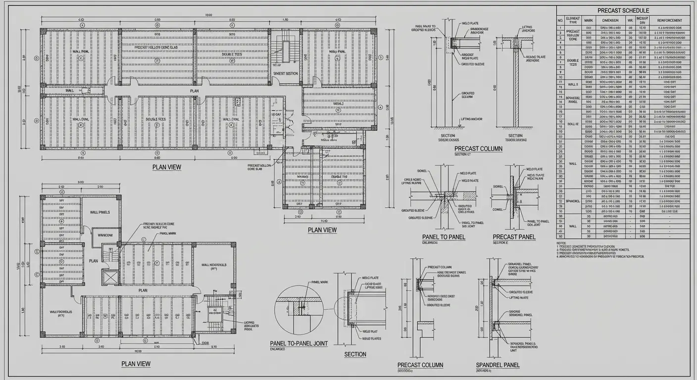
Precast and modular
Panel and module geometry modelled with the joints, tolerances and connections the plant needs, including the embeds that have to be cast in correctly the first time.
How We Work
How a structural package runs
From the engineer's design and your template through to files issued into your CDE.
Scope and standards intake
We read your EIR or BEP, template, shared parameters and naming convention, then confirm in writing what we will model, at what Level of Development, and every assumption we had to make.
Template and content check
Your template is tested before we rely on it: worksets, view templates, filters, host behaviour and schedule drivers. A fault here multiplies across every sheet, so it is cheapest to find now.
Pilot package
One representative level, zone or system is produced end to end under full production QA, so you judge the real service before committing volume.
Discipline modelling
Architectural, structural, MEP and civil elements built to the agreed LOD in your template, with the geometry and data your downstream uses actually need.
Interdisciplinary check
Models are federated and reviewed against each other as we go, so conflicts surface during production rather than at the coordination milestone.
Documentation and data
Sheets, schedules and parameter data generated from the model, named and structured to your convention.
Three-gate QA
A modeller self-check against the project checklist, an independent reviewer who did not build it, then a lead sign-off against your standards and LOD.
Delivery into your CDE
Native and exchange files issued into ACC, BIM 360 or wherever you work, purged and audited, with the QA record attached.
Our Benefits
What you actually get
What changes when a structural model is built for the fabricator rather than for a view.
Reviewed by a registered architect
Aercon is architect-led — a registered architect oversees delivery, so your model is questioned on design and constructability, not only geometry. Sealing and professional responsibility stay with your professionals of record.
Your template, not ours
We work inside your template, shared parameters, naming convention and BIM Execution Plan. Nothing comes back needing to be re-mapped to your standard.
Modelled for the use, not the picture
Elements are built to the agreed Level of Development with the data your schedules and downstream trades actually need, so the model survives past the render.
Cross-discipline checks during production
We federate and check as we go rather than waiting for the coordination milestone, so conflicts are found while they are still cheap to fix.
A QA record, not a QA claim
Three gates before anything leaves: modeller self-check, an independent reviewer who did not build it, then lead sign-off. The signed checklist ships with the deliverable.
Your drawings stay yours
NDA before we receive anything, access limited to the named project team, and we never reuse a client's models, families or drawings for anyone else.
Our Work
Structural BIM Projects
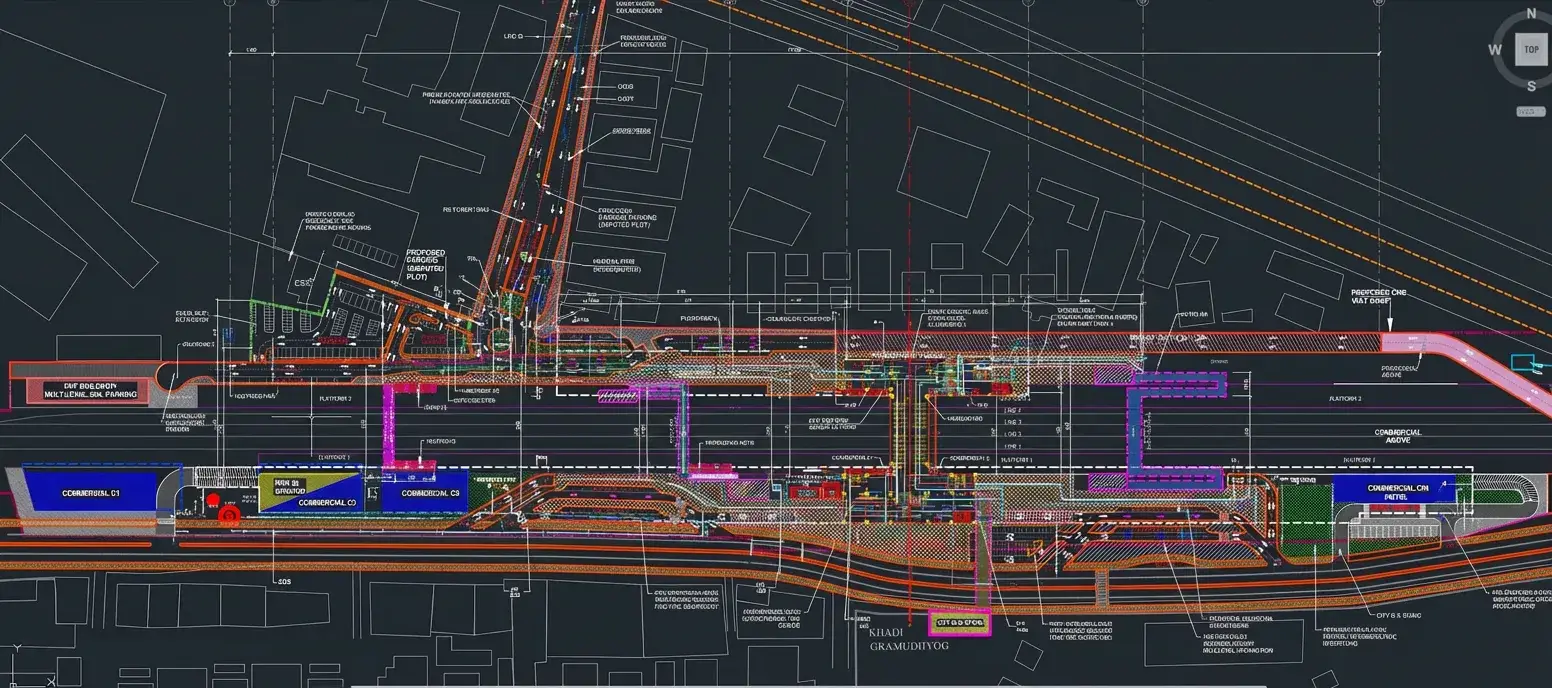
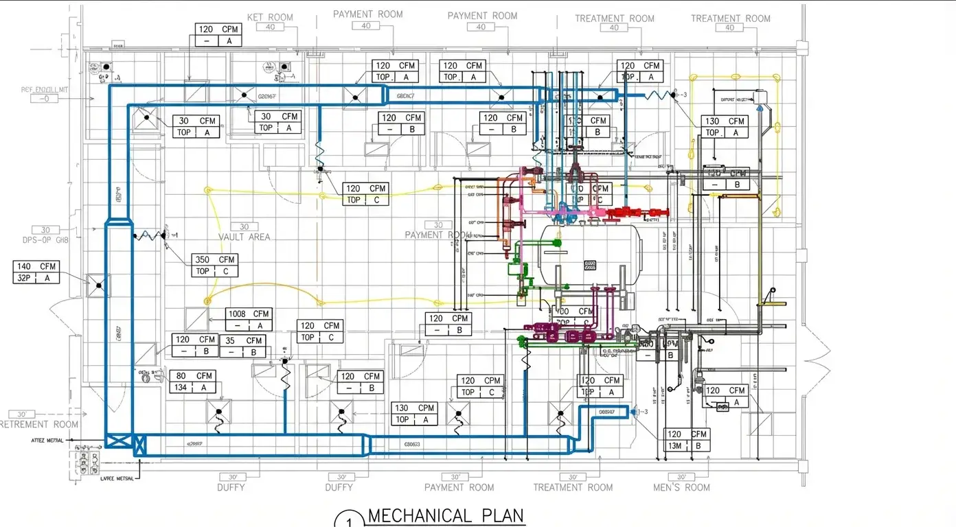
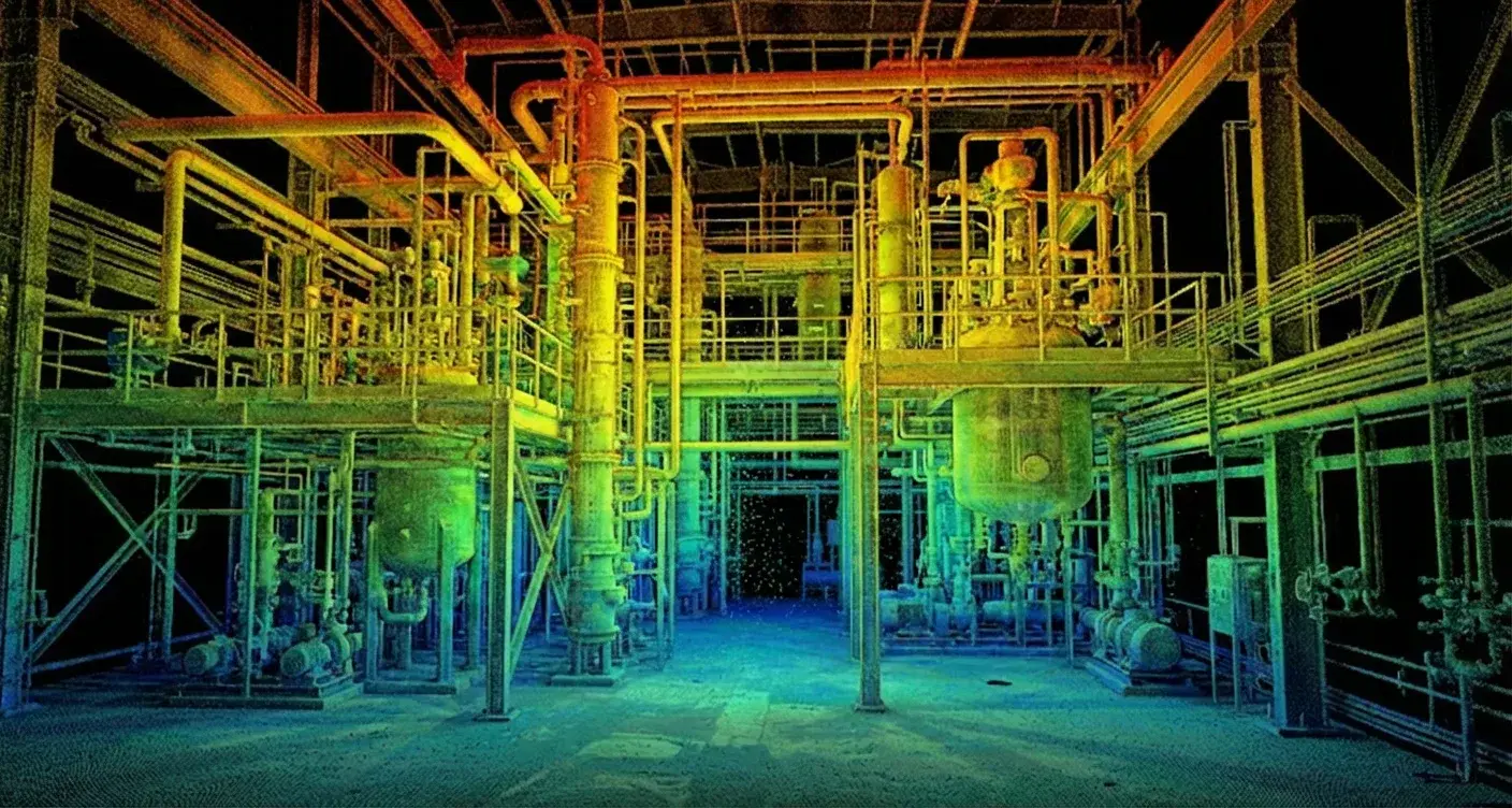
Framing, foundation and detailing work from recent packages.
Sectors
Industries We Serve
Delivering BIM excellence across diverse sectors with tailored solutions.
FAQ
Frequently Asked Questions
Need a structural package modelled or detailed?
Send the design drawings, your template and the fabricator's standard, and we will scope it.